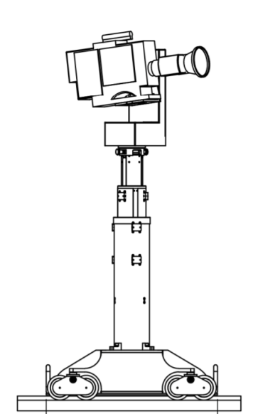
SPIRIT DOLLY
Presentation of the material
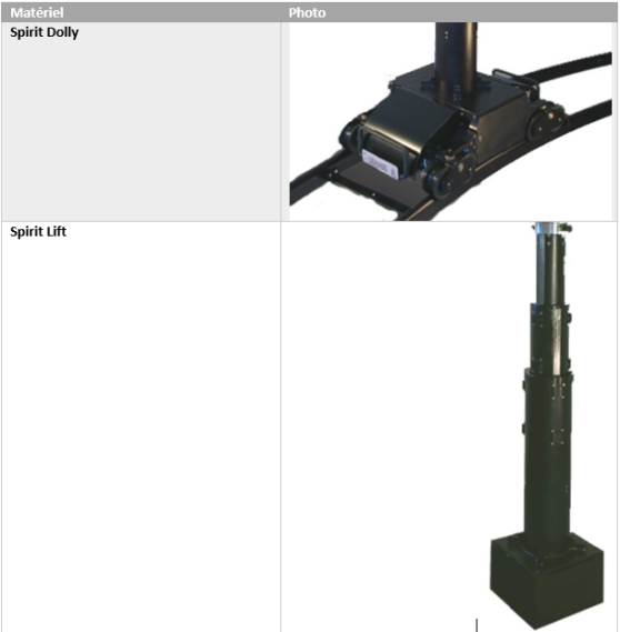
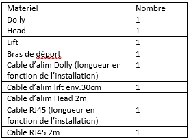
Here is a list showing the material used in this documentation:
Here is a list showing the material used in this documentation:

Complete list of equipment
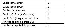
The following lists detail the hardware needed and to be added depending on the desired configuration.
Material dolly + lift + head (without camera)
+tracking
+ Genlock (with generator and distributor)
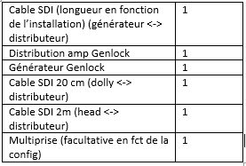
+ IP camera
If Head + integrated switch
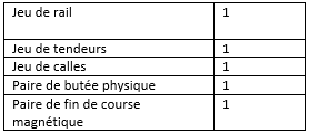
Tracks:
Installing the rails
Installation of the rails
Position the rails according to the floor plan
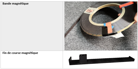
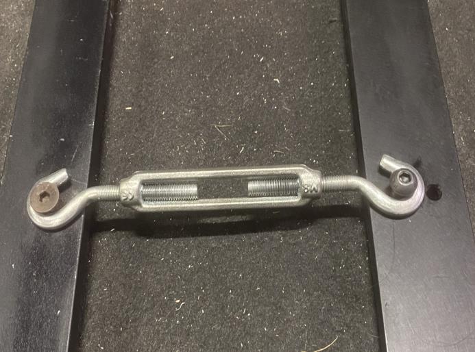
Installing tensioners
Add a rail tensioner between each rail to allow the play between the rails to be limited as much as possible. Be careful, do not tighten with all your strength, it can be bad for the rails and the tensioner.
Rail leveling
Once the rail is in place, make sure that the rails are horizontal with a spirit level. To correct any defects, add shims under the rails
Installation of magnetic tape
Position staples by clipping them approximately every 30 cm. Then add the magnetic strip by sliding it into the clips
Added Dolly
Add the Dolly to the rail.
Setting up physical stops
Add the physical stops by tightening them sufficiently hard.
Installation of end of races
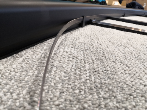
Place the end of run flags approximately 60 cm before the physical stops. Care must be taken to properly align the sensor with the flag (see photo). Attention, to know if the limit switches are correctly installed, it will be necessary to check that the sensors are activated when the Dolly passes over the flags (once the Dolly is powered up). This will be recalled in the “checks” chapter.
Installing the Dolly
Placement of the lift
Place the column, be careful there is a direction not to touch the components of the Dolly housing. Use the drawing on the bottom of the housing to position the column in the right direction.
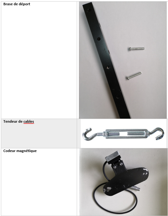
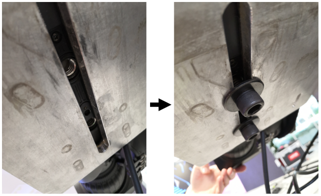
Setting up the offset arm
The offset arm ensures that the cables do not fall on the rail. It can be placed to deport the cables to the left or right of the rail. It is important to clearly identify on which side to put the offset arm and therefore on which side the cables will be. There is no right answer as to which side to choose, it depends on the installation. However, it is more interesting to place the cables on the interior side in the case of curved rails to limit their path as much as possible.
Place the offset arm above the sockets as in the photo below.
Then place the hand screws to hold the offset arm and the column in position.
Setting up Head
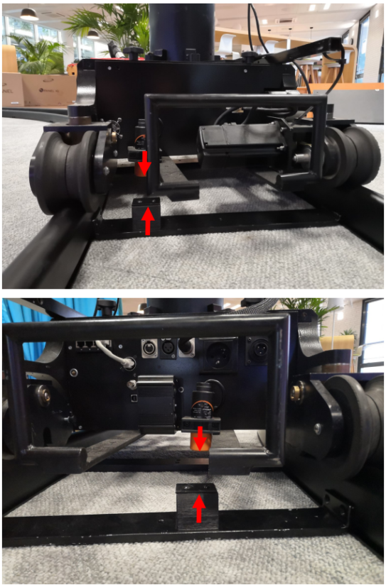
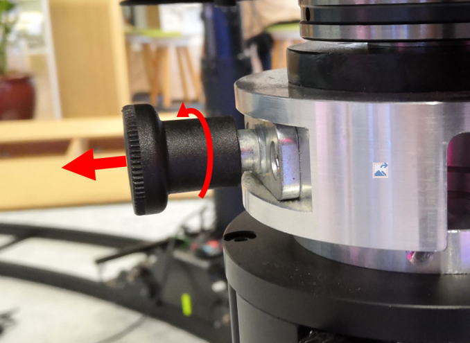
To set up the Spirit Head on the lift, lock the 2 pins in the open position by pulling them and turning them 90°
Then place the head on the lift, making sure to align the holes as in the photo below
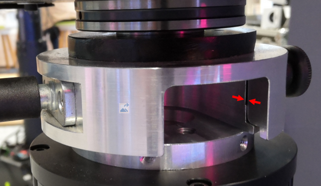
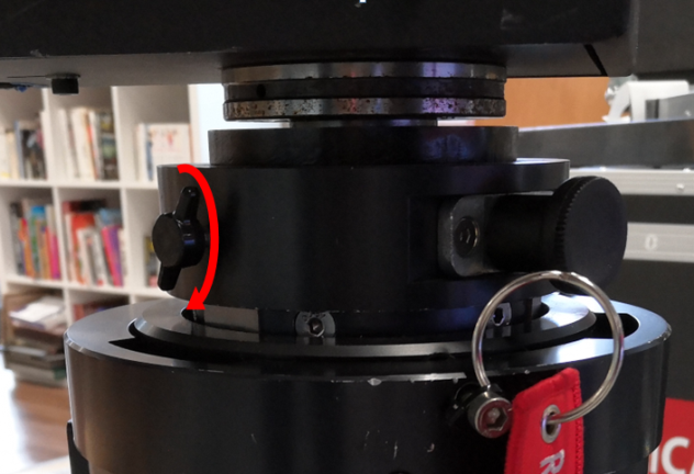
Replace the pins by turning them the other way. If the Head is correctly placed, the pins sink into the lift and hold it in position. Finish by tightening the small screw located between the 2 pins (see photo below)
Setting up the camera
Place the camera with its Optics on the Head so as to center its weight on the platform. (The equilibrium position is as horizontal as possible). This step is important to limit the effort on the tilt motor. Attention however, Depending on the geometry of the optics, the travel around the tilt can be reduced. It is then necessary to limit via the web interface the stroke to avoid damaging the optics.
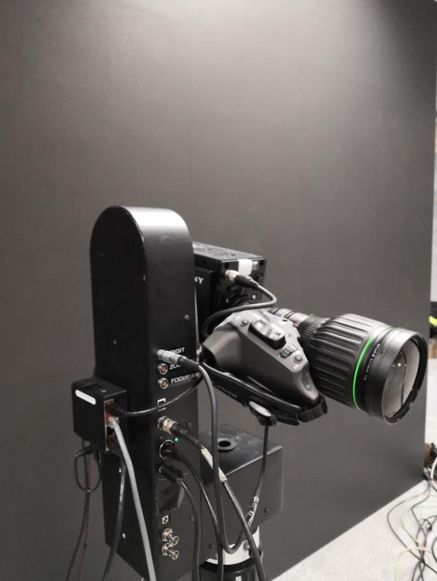
Once the camera is correctly positioned, tighten the screws under the camera to secure it to the Head as in the photos below.
Dolly wiring:
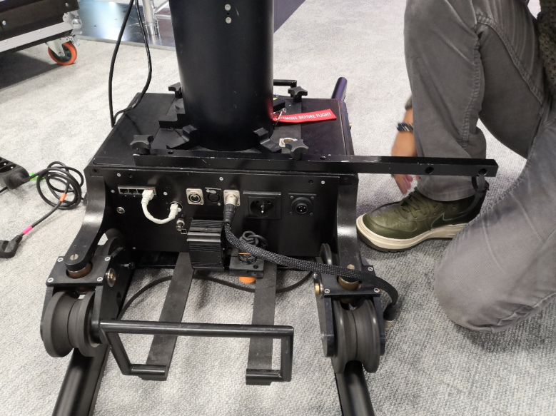
Connections at Dolly level
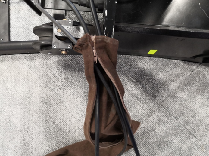
Once you have all the necessary cables pass them through the sock as in the photo below:
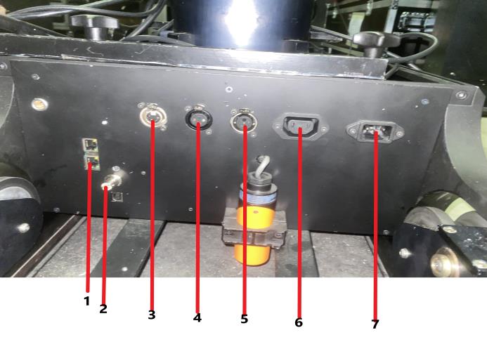
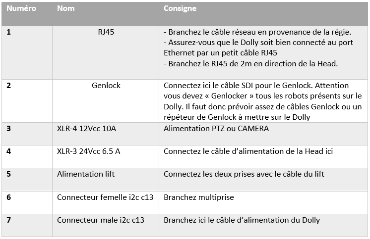
The photo and the following table summarize the connections to be made on the Dolly.
Connection at head level
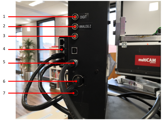
The photo and table below summarize the connections to be made at the Spirit Head
Camera and optical connections
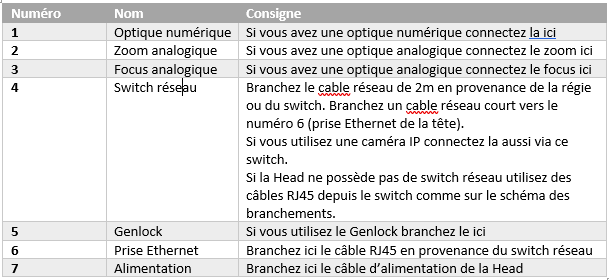
The connections are specific to the camera used. It is possible that the camera power cable is too short when the lift column is at its maximum amplitude. In this case, the power supply must be placed as close as possible to the camera by taping it to the column, for example:
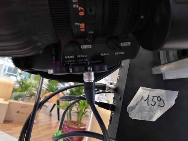
If you have digital optics, the photo below details where the digital optics cable from the Head connects:
Genlock
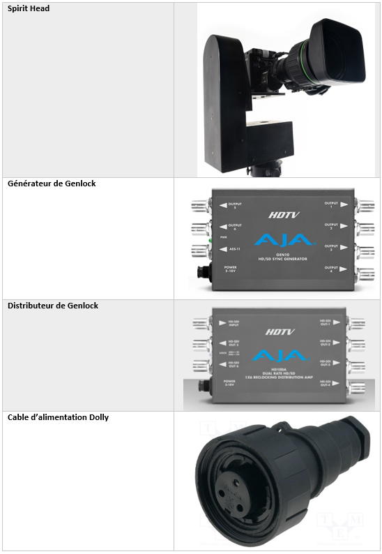
If you use the Genlock, you need 2 boxes: 1 "generator" box which will generate the signal and 1 "amp distribution" box which will allow you to repeat and distribute the signal. They look like this:
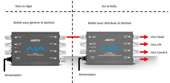
The diagram above shows a possible wiring of Genlock. The first box that generates the signal is located in the control room so that it can be used on other devices. It is transmitted by an SDI cable passing through the sock to the Dolly where it is recovered by the distribution box. Each device on the Dolly is then connected to this box.
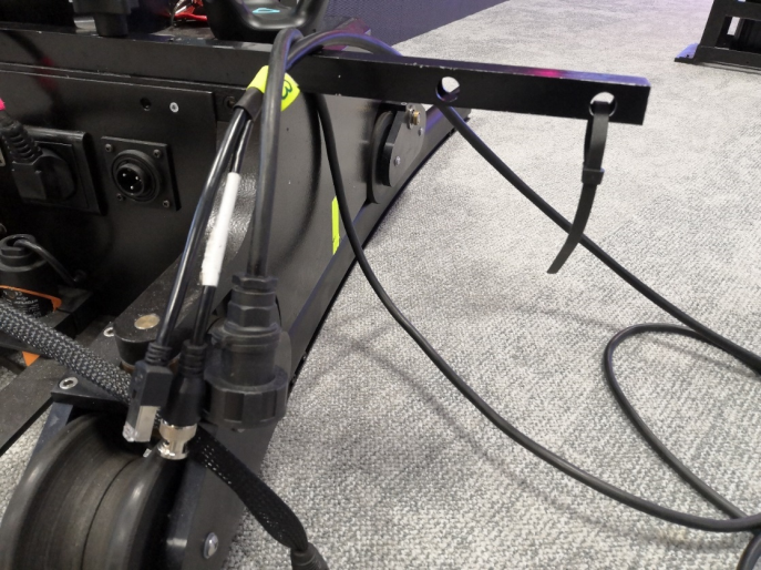
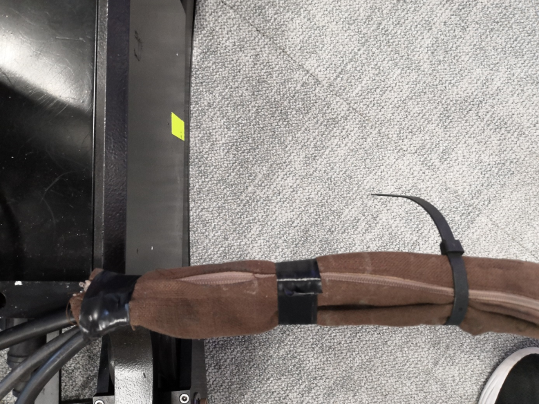
Now that all the cables connecting Dolly and the control room are installed, they can be tied together with a piece of tape approximately every meter. You can then close the sock along the cable. The sock must then be fixed along the offset arm with clamps or tape.
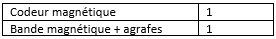
Install a magnetic encoder:
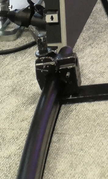
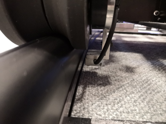
The magnetic encoder is placed on the wheel close to the encoder socket. The connection is detailed in the photo below. The encoder must then be fixed with 2 screws at the level of the wheel. It can be put inside the rail (as pictured) or outside depending on where the magnetic strip was installed.
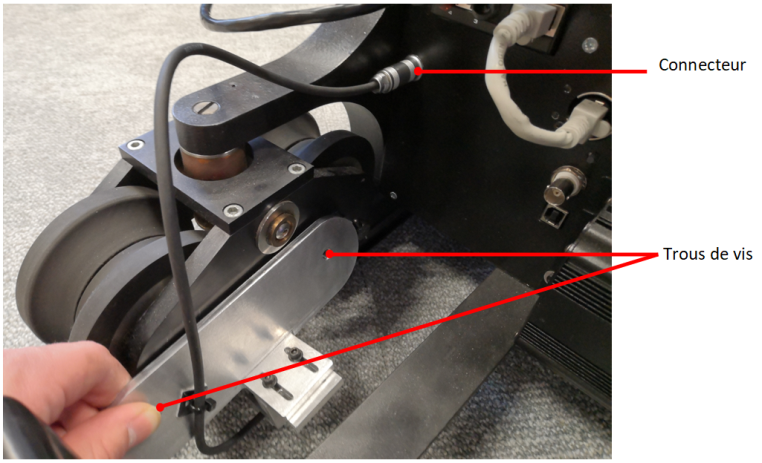
Once the sensor is installed, tighten the set screws so that the sensor is facing and spaced approximately 3mm from the magnetic strip.
Verifications
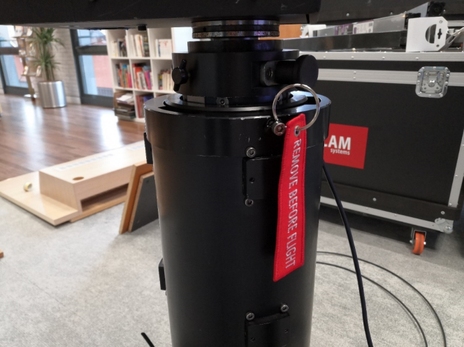
Check that there is no “remove before flight” flag on the lift (see photo below). This flag mechanically blocks the column. It must therefore be removed before launching the Dolly.
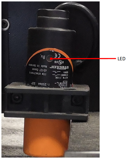
Once the Dolly has been powered up, bring it close to the limit switches and check that the LED on the sensor lights up when the Dolly passes over the limit switch. If it does not light, raise the end of the race with shims.
Network Setup
There are multiple possible configurations to control the Dolly. We will detail here how to access the web interfaces of the Dolly and the Head
Setting up the network
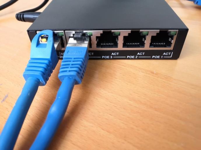
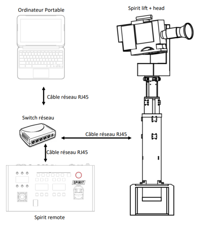
At the control room, install a network switch (see photo below) and connect the RJ45 network cable from the Dolly to it.
Also connect a laptop or Multicam here. If you have one, you can also connect a control desk. Here is a possible installation scheme (the computer can be replaced by a multicam):
For further network configuration, click here:Network SetupSetup